
目录
测试自动继电器的分步指南
汽车继电器、卡车继电器和车辆继电器接线是车辆电气系统的组成部分。它们充当打开和关闭电路的开关,控制前灯、空调和燃油泵等功能。当这些继电器发生故障时,可能会对您的车辆性能造成严重问题。因此,了解如何测试这些组件以确保它们正常运行至关重要。
| 编号 | 产品 |
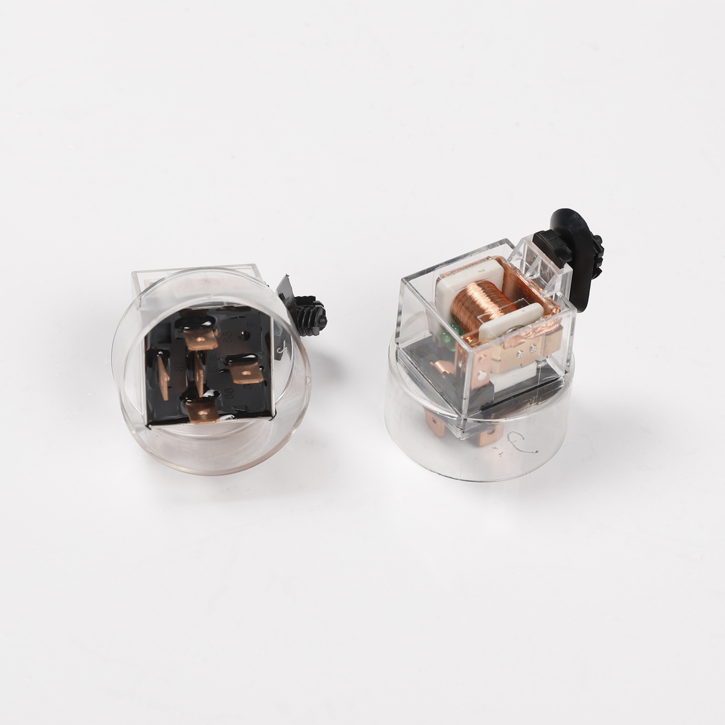
| 8 | 自动继电器 |
测试自动继电器的第一步是找到它们。车辆手册通常会提供指示继电器位置的图表。它们通常位于保险丝盒中,保险丝盒通常位于引擎盖或仪表板下方。找到继电器后,将其从插座中取出。
To measure the resistance, connect the multimeter’s probes to the relay’s coil Terminals. These are typically the two smallest terminals on the relay. If the resistance is within the expected range, the coil is functioning correctly. However, if the resistance is significantly higher or lower, the coil may be damaged and the relay will need to be replaced.
After testing the coil, you should test the relay’s switch. To do this, you will need a 12-volt power source, such as a car battery or a power supply unit. Connect the power source to the relay’s coil terminals, then set the multimeter to the continuity setting, usually denoted by a wave or diode symbol. This setting will allow you to determine whether electricity can flow through the relay’s switch.
| Nr. | Designation |
| 7 | Flasher Relay |
Connect one of the multimeter’s probes to one of the relay’s switch terminals, and the other probe to the other switch terminal. If the multimeter indicates that there is continuity, or a complete electrical circuit, the switch is functioning correctly. However, if the multimeter indicates that there is no continuity, or an incomplete electrical circuit, the switch is faulty and the relay will need to be replaced.
In addition to testing the relay itself, it is also important to test the vehicle relay wiring. Damaged or corroded wires can prevent electricity from reaching the relay, causing it to malfunction. To test the wiring, set the multimeter to the voltage setting, usually denoted by a V. Connect the multimeter’s probes to the wire and the vehicle’s ground. If the multimeter indicates that there is voltage, the wire is functioning correctly. However, if the multimeter indicates that there is no voltage, the wire may be damaged and will need to be repaired or replaced.
In conclusion, testing Auto Relays, Truck relays, and vehicle relay wiring is a straightforward process that can be performed with a multimeter and a 12-volt power source. By regularly testing these components, you can ensure that your vehicle’s electrical system is functioning correctly and prevent potential issues before they become serious problems.
Understanding and Implementing Vehicle Relay Wiring Techniques
Understanding and implementing vehicle relay wiring techniques is a crucial skill for anyone involved in auto repair or maintenance. This article will guide you through the process of testing auto relays, truck relays, and general vehicle relay wiring, providing you with the knowledge you need to diagnose and fix electrical issues in your vehicle.
Auto relays, also known as automotive relays, are essential components in a vehicle’s electrical system. They act as Switches that turn electrical circuits on and off, controlling functions such as the headlights, Windshield Wipers, and fuel pump. Similarly, truck relays perform the same function but are typically designed to handle higher electrical loads due to the larger size and power requirements of trucks.
Testing these relays is a straightforward process that requires a multimeter, a device that measures electrical properties such as voltage, current, and resistance. To begin, locate the relay you wish to test. This is typically found in the fuse box, which is usually located under the hood or dashboard of the vehicle. Once you’ve located the relay, remove it from its Socket.
Next, set your multimeter to the resistance setting, usually denoted by the Greek letter omega (Ω). Connect the multimeter’s probes to the relay’s coil terminals, which are usually labeled as 85 and 86. A functioning relay should display a resistance between 50 and 120 ohms. If the reading is outside this range, the relay is likely faulty and should be replaced.
After testing the coil, it’s time to test the switch part of the relay. For this, you’ll need to supply power to the coil terminals using a car battery or power supply. Connect the positive terminal of your power source to terminal 86 and the negative terminal to terminal 85. You should hear a click, indicating that the relay’s switch has activated.
| Nr. | Products |
| 5 | Automotive Relay |
Now, set your multimeter to the continuity setting, usually denoted by a wave or diode symbol. Connect one probe to terminal 30, which is the common terminal, and the other probe to terminal 87, which is the normally open terminal. If the relay is functioning correctly, the multimeter should indicate continuity, meaning there is a complete electrical path between the two terminals. If there is no continuity, the relay is faulty.
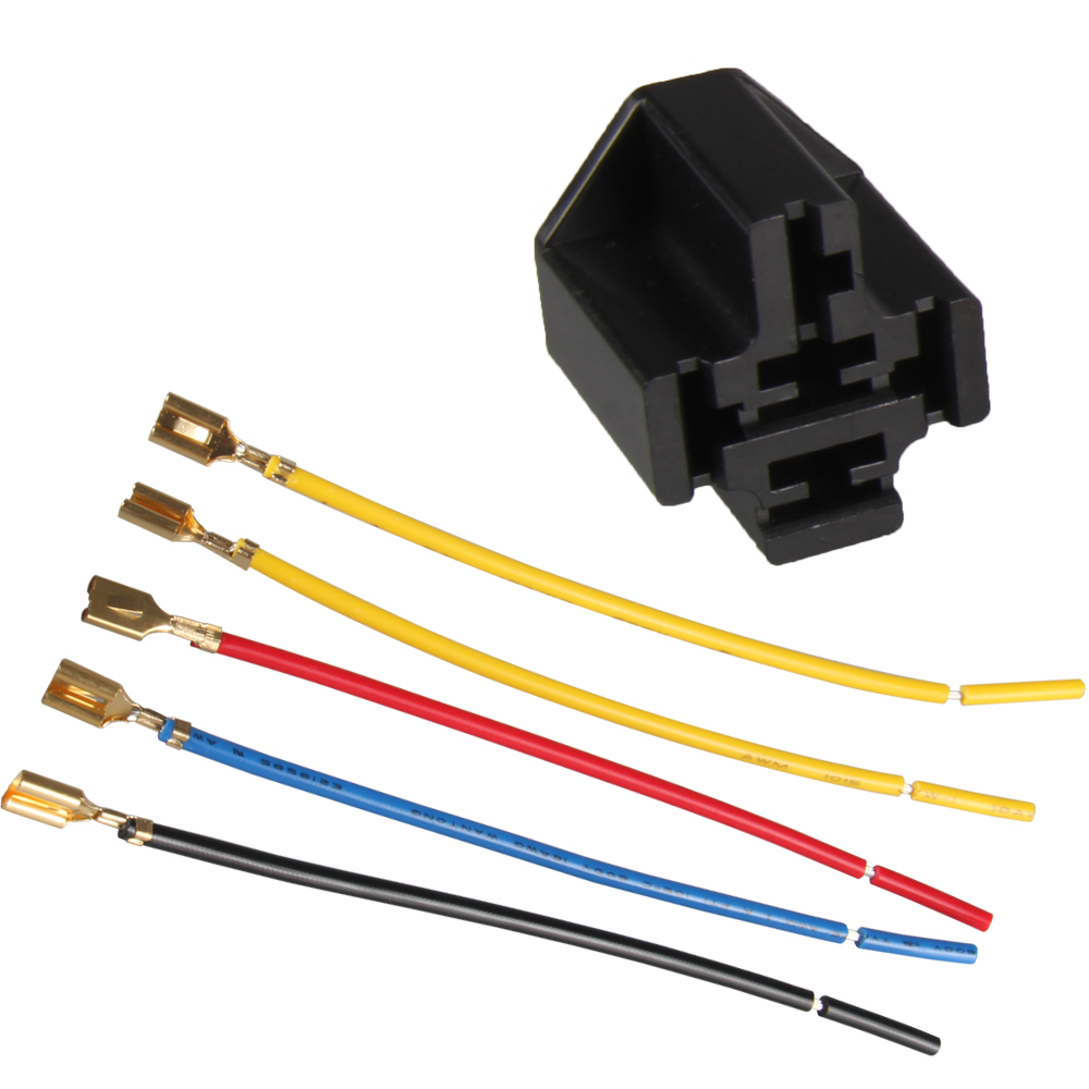
Vehicle relay wiring is another important aspect of auto and truck maintenance. The wiring of a relay involves connecting the various terminals to the appropriate parts of the vehicle’s electrical system. Terminal 30 is usually connected to the battery, terminal 85 to the ground, terminal 86 to the control switch, and terminal 87 to the device being controlled by the relay.
Understanding and implementing these vehicle relay wiring techniques can save you time and money on auto repairs. By testing your auto and truck relays regularly, you can catch and fix electrical issues before they cause more serious problems. And by knowing how to wire a relay, you can replace faulty relays yourself, avoiding the cost of a professional mechanic. With a little practice, these skills can become a valuable part of your auto maintenance toolkit.